Making a part in Fritzing 0.8.7b
Before we get started, it’s worth mentioning that the Fritzing site has a page on making parts with a bunch of tutorials:
http://fritzing.org/learning/tutorials/creating-custom-parts/
However, they point out quickly that as of version 0.7.9, many of those tutorials are outdated, due to changes mentioned in this blog post:
http://blog.fritzing.org/2012/10/09/new-parts-editor-released/
The most notable is that you can not create completely new parts. You can only modify existing parts. When I was trying to build a part in Fritzing, I was traveling and temporarily had no internet, so not knowing this was quite confusing! But once you realize this fact, it makes it a lot easier to move forward.
I needed to make a part for this DC-DC converter:
http://www.power-one.com/sites/power-one.com/files/documents/power/datasheet/yev09t10_v5.pdf
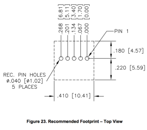
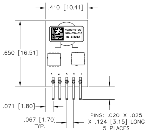
The main reason I needed a PCB at all is that the pins are very close together, 67mil apart according to the mechanical design.
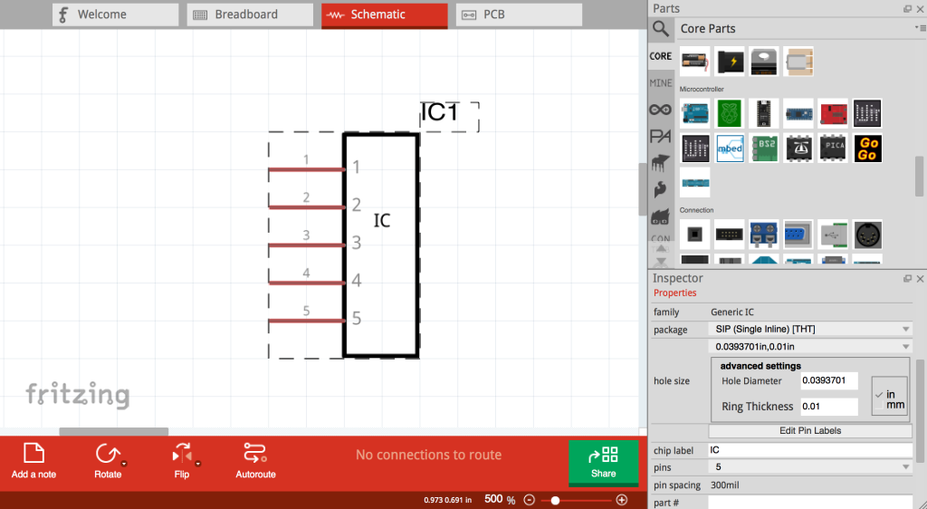
I created a new Sketch, clicked the Core set of parts, and dragged a DIP – 8 pins to the sketch.
I went into the Inspector and changed the package to SIP (Single Inline) [THT], set hole size – ring thickness to 0.01, and set the pins to 5.
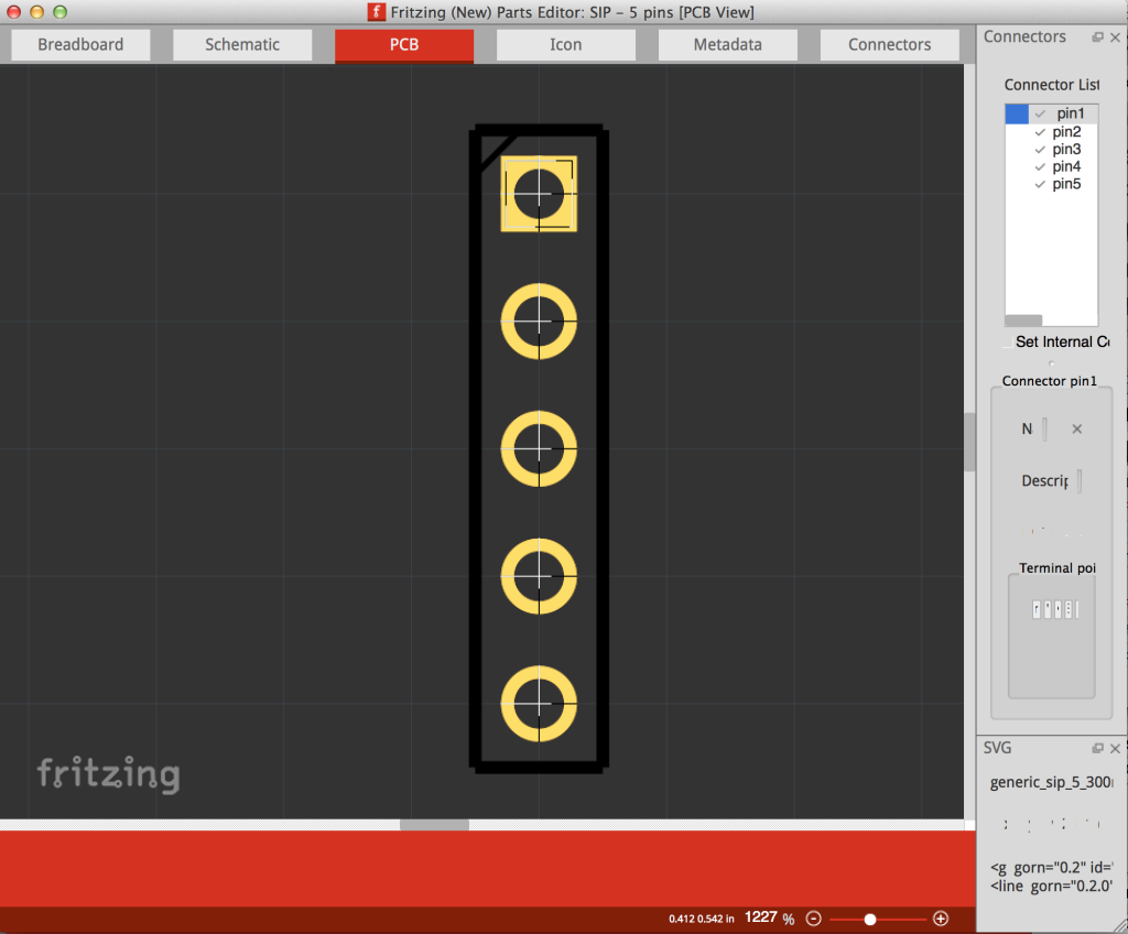
Right click on the part in the sketch window and click Edit (new parts editor).
Click on the PCB tab. This is what the board will actually look like when it’s laid out, so the spacing of the holes is quite incorrect. The layout is stored as vector in SVG format, so we need to export it and modify the vectors.
File > Export > as Image > SVG.
Inkscape on a Mac is a bit frustrating to install now as Apple got rid of the X11 server that it runs on. Fortunately it is open sourced as XQuartz and there’s a tutorial on how to install it and get Inkscape up and running here:
http://www.rightnowintech.com/2012/08/how-run-inkscape-on-os-x-mountain-lion.html
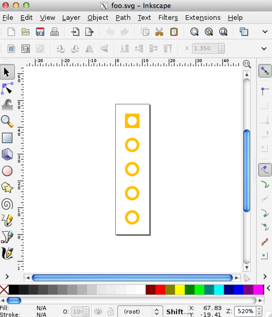
Here is our file in Inkscape:
The first thing we want to do is resize the footprint to be the size of the part we’re creating.
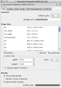
So we go to File > Document Properties and set the width to 0.41 inches and the height to 0.4 inches.
Also while we’re in there let’s make sure Default units are set to inches.
Now our footprint looks like this:
Of course the pads are all wrong so now we have to move them around one by one to the correct locations.
For some reason the parts we want to modify tend to be deep inside nested groups. Let’s ungroup all the groups which contain the copper. Sometimes you have to just keep right clicking and clicking ungroup until you get to the point where you can see all the objects as separate. When I did that I found there was a copper0 object and a copper1 object. copper0 is for the top of the board and copper1 is for the bottom of the board.
We’re at the circle, now we want to pick where it goes on the screen.
According to the footprint the first circle is 0.071 inches, or 71mil from the edge.
One frustrating thing is that the location of the circles is based on the lower left hand corner of the circle, but the mechanical diagram we’re working off of bases the locations on the center of the circle. So we have to compensate by subtracting the radius of the circle, approximately 0.2, to the X and Y location.
For X:
0.071 – 0.02 = 0.051
0.138 – 0.02 = 0.118
0.205 – 0.02 = 0.185
0.272 – 0.02 = 0.252
0.339 – 0.02 = 0.319
For Y (all the Y’s are the same):
0.22 – 0.02 = 0.2
So this is close to our footprint here.
Another weird bug is that the colors of the exported file don’t seem to conform to Fritzing’s graphic standards:
http://fritzing.org/fritzings-graphic-standards/
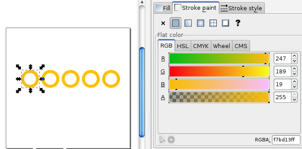
The colors for the copper should come out as hex f7bd13ff, and the lines at the borders appear black in Fritzing, but instead the copper comes out as FFBF00.
If you try and import it back in it doesn’t recognize the copper and your holes don’t show up.
So let’s fix the colors:
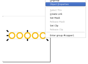
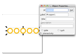
Now we create the copper1 group. Select all the circles at once, Object > Group.
Then right click > Object Properties, and set the name to copper1, and the tag to #copper1.
I can’t see the silkscreen all that well because it’s white, but I resized it to the size of the footprint. When it gets back into Fritzing it shows back up as white lines.
If we want the pads on the top layer too we copy this object and name the group copper0.
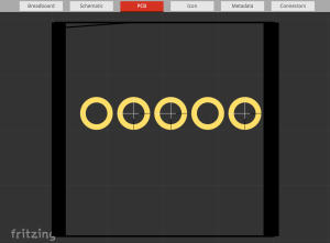
Finally done making the vector file. Save the file, go back to the new part view in Fritzing, File > Load image for view, pick the file, and bam:
Make sure that you click on all the pins on the menu on the right and they show up where you’re hoping. I got burned on this the first time and had to go back and start all over.
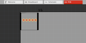
At this point the part is usable in the PCB view of the sketch!
I think this software still has a lot of bugs as a platform for making PCBs, but it’s getting a lot closer than it was the last time I looked at it.

